Modeling horizontal stress
On the Horizontal Stress form (MODEL > Geomechanics > 3D Grid Geomechanical Properties > Horizontal Stress) you can model the distribution of horizontal stress (Shmin and SHmax) in the 3D grid based on effective stress ratio or total stress ratio.
All cells of the selected 3D grid will be filled with a horizontal stress property value. The modeling does not use interpolation or simulation of the stresses themselves.
To calculate horizontal stress
-
Select the 3D grid and its properties:
3D grid Select the 3D grid that you want to populate with horizontal stress property.
Overburden Select an overburden property of the 3D grid. The property needs to be of type 'Overburden Stress' and located under the selected 3D grid to show up in the drop-down list.
Pore pressure Select a pore pressure property of the 3D grid. The property needs to be of type 'Pressure' and located under the selected 3D grid to show up in the drop-down list.
- Select one of the three options:
- Constant ratio Set constant stress ratios for the entire grid.
- Well profile Use the stress ratio profile from a single well. The ratios will be projected horizontally and are therefore constant at depth, see right image below.
- Grid ratios Use stress ratios that were previously populated along the grid. The ratios are subject to layering. The distribution of the ratios can then be subject to truncation, see left image below.
- In all cases you have to specify or select the input ratios and to specify the type of stress ratio: Effective stress ratio or Total stress ratio.
- Only for Grid ratios:
- Property suffix Smoothing creates a new smoothed ratio property: enter a suffix for this smoothed ratio property. The name of the new property is ‘<selected Shmin/SHmax ratio property name> smoothed’.
- Distance Specify a distance from selected fault(s) inside of which all cells are emptied and then filled with smoothed values.
- Select faults to use Select the fault around which you want to smooth the ratio properties.
- Click Apply to start the calculation and keep the form open or OK to start the calculation and go to the next form. The resulting stress properties SHmax and Shmin appear in the JewelExplorer in the Static Geomechanical Properties folder under the grid that you selected in Step 1. Note that Shmin and SHmax are total stresses.
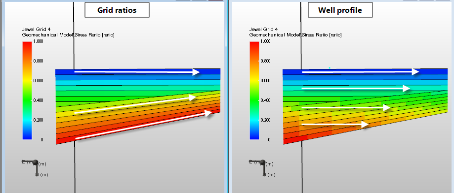
Populating the grid with stress ratios. Left: Stress ratios populated along the grid. Ratios are subject to structure and truncation. Right: The stress ratios are populated from a single well profile and are projected horizontally onto the grid click to enlarge
The presence of faults or unconformities can lead to non-linear steps in the stress ratios, and thus to a non-linear horizontal stress distribution across the discontinuity surface. To exclude this effect, you can first smooth such non-linear ratio properties. Inspect the ratio properties in the 3D view to see whether smoothing is necessary.
On the Grid ratios tab, select the Create smoothed ratios first option and specify the following smoothing settings:
To carry out the smoothing, click Smooth around faults.